Ionicon PTR-QMS
Ionicon PTR-QMS
Disclamer: more general info about the instrument will follow once I got experience using it.
I got a new very special toy, you might ask:
What is so special about this instrument?
Usually, when we think about residual gas analysis we think of electron Ionization with an Ion source looking similar to the one presented in CAS tutorial on RGA Essential Knowledge.
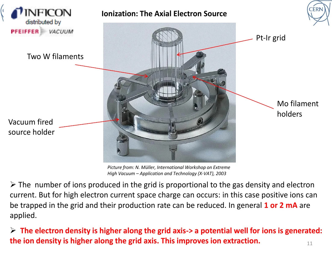
But this instrument does this, as you might have already guessed, a bit different: instead of bombarding molecules with electrons (we are talking about energies of ~50 - 200 eV) this uses a chemical reaction, called the proton transfer reaction (PTR) so let’s quickly look into that.
For a detailed look at this I’d recommend the Introduction Manual.
\(H_3 O^+\) Ions are generated in a plasma discharge chamber, those are then fed into a drift tube where the \(H_3 O^+\) Ions will mix with the sample air and thus will try to “hand over” their additional proton. The important Value here is the “proton affinity”, this is basically saying how hard your molecule clings onto its additional proton. \(H_3 O^+\) has a proton affinity of 7.22 eV and can “hand over” the proton to everything with a higher proton affinity.
Here are some proton affinities to get a feeling for the parameters (taken from the Introduction Manual)
| Component | Proton Affinity [eV] | Component | Proton Affinity [eV] |
|---|---|---|---|
| \(H_3 O^+\) | 7.22 | \(H_2S\) | 7.4 |
| \(He\) | 1.8 | \(HCN\) | 7.4 |
| \(Ar\) | 3.8 | \(C_6H_6\) | 7.8 |
| \(N_2\) | 5.1 | \(C_3H_6\) | 7.8 |
| \(CO_2\) | 5.7 | \(C_2H_5OH\) | 8.2 |
| \(N_2 O\) | 5.9 | \(NH_3\) | 8.8 |
For further data I’d recommend the NIST Chemistry WebBook
A pattern we can observe is that this MS is no good for residual Gas analysis, but instead is really made for big, organic molecules in gas phase. The big advantage is that we are not dealing with 100s of eV, but rather small energies and thus minimize fragmentation, which is awesome cause we can just sniff a sample and not worry too much about where the molecules might fragment when bombarded.
My variant of the quadrupole built into the MS (A Pfeiffer QMG 422 System) with a mass range of 0 - 512 amu and a resolution of about 1 amu.
The Pfeiffer Quadrupole system
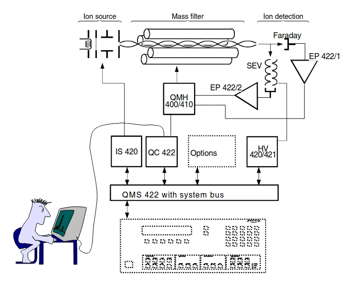
This schematic can be found in the manual. The PTR-MS has it’s own Ion source, thus we do not have the IS 420 option installed.
The main focus will be the QMH-400 RF Frequency generator for the quadrupole. If you want to know more about how the generated mix of AC and DC voltage is able to achive mass filtering I’d recommend watching my talk about quadrupole mass spectrometers or reading the lecture notes.
What’s wrong with it?
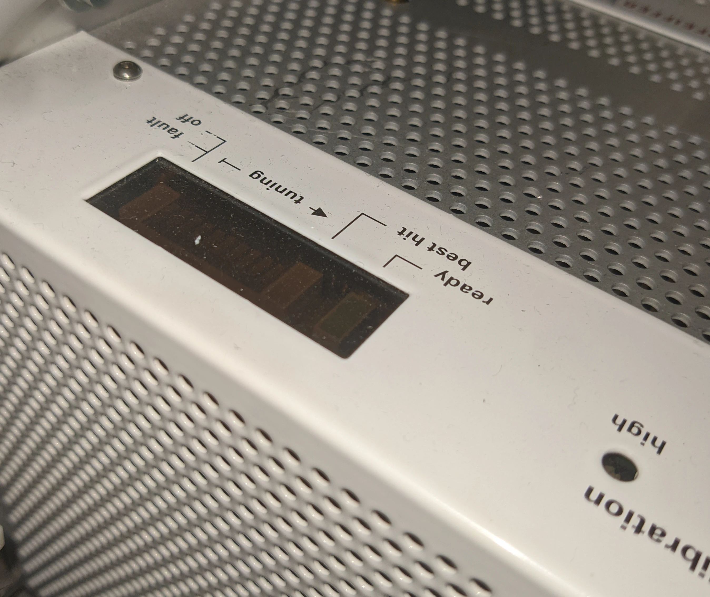
When turning on my instrument for the first time no magic smoke escaped, but there was one obvious problem: the QMH-400 Quadrupole RF generator did not power on, the LEDs on it stayed dark.
The PSU supplying power to the QMH-400 (located inside the QMS-422) was continusly supplying around 52V on its 24V output. A quick look inside showed some burn marks on the secondary modules.
I had a similar power supply on hand and put it in place of the broken one. The QMH-400 powered up and showed no errors in the software, but something did not look right when looking at the spectrum.
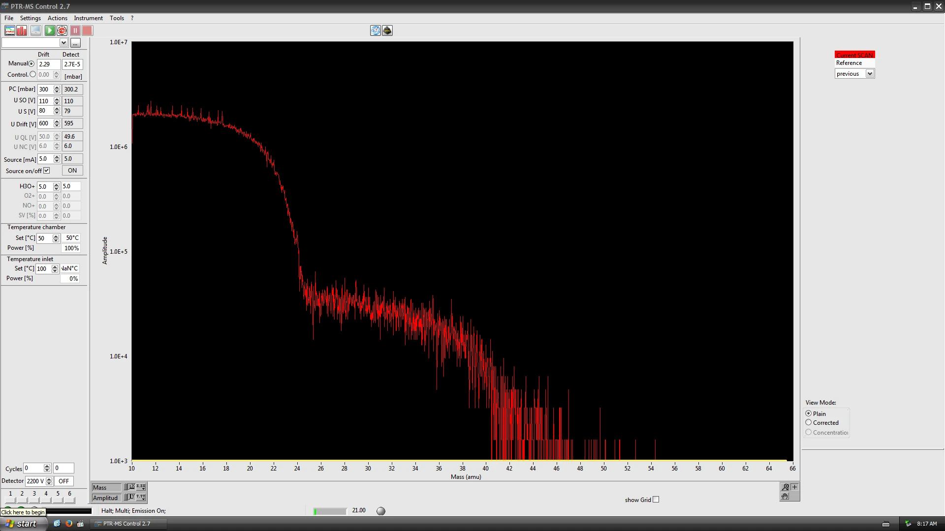
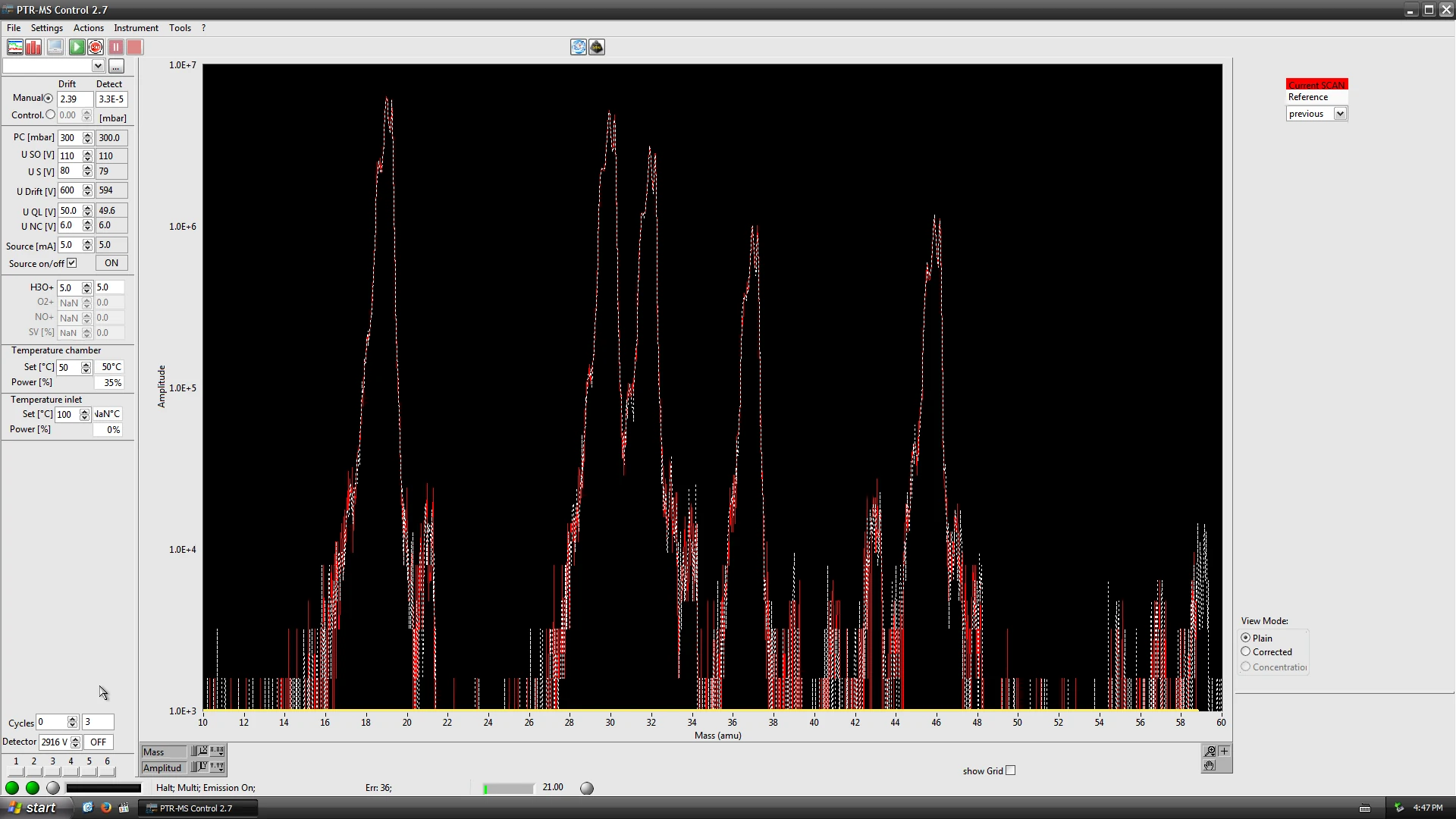
As described in a post by me a spectrum looking like the one above is an indication for a broken DC voltage. The DC voltage acts as a sort of “high pass filter” for masses, because very light ions will be deflected more by a constant field than heavy ones \(F = m a = q E\). With just the AC field remaining we only have a variable low pass filter, this is exactly what we observe in the spectrum.
With this in mind I started by disassembling the Pfeiffer QMH-400 RF Frequency generator, it consists of 3 big PCBs:
- CC-400-5: generating the needed voltages for the QMH-400 from the supplied +/- 24V
- DC-400-5: DC offset voltage
- RF-400-5: AC voltage
CC-400-5 and DC/DC board
The CC-400-5 can be found at the “tip” of the QMH-400. It is the board supplying power to all other boards and taking over some control tasks.
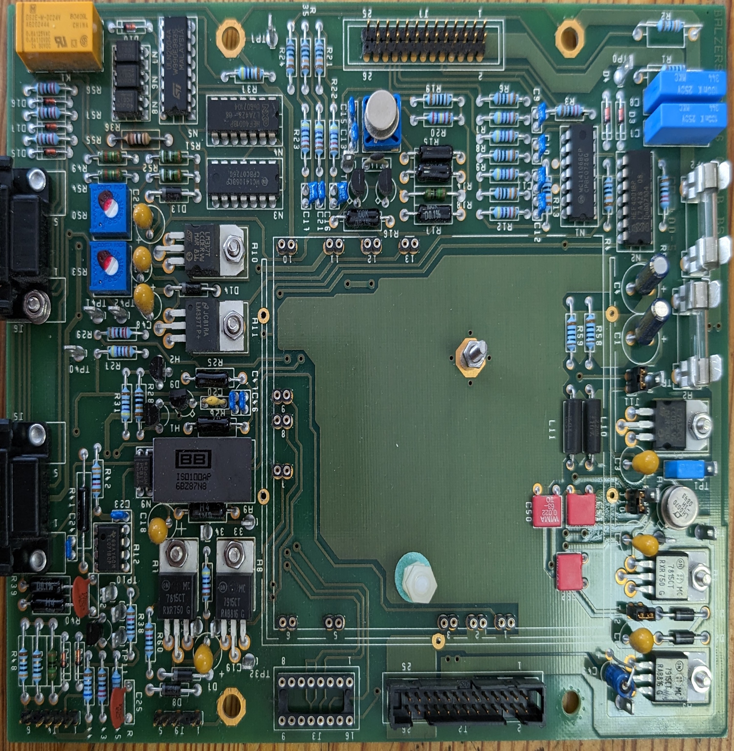
During probing on the CC-400-5 board I found that the entire left area on the picture did not seem to get any power. The linear regulators on the left side are supplied from a board on pin headers, the DCDC-CO board:
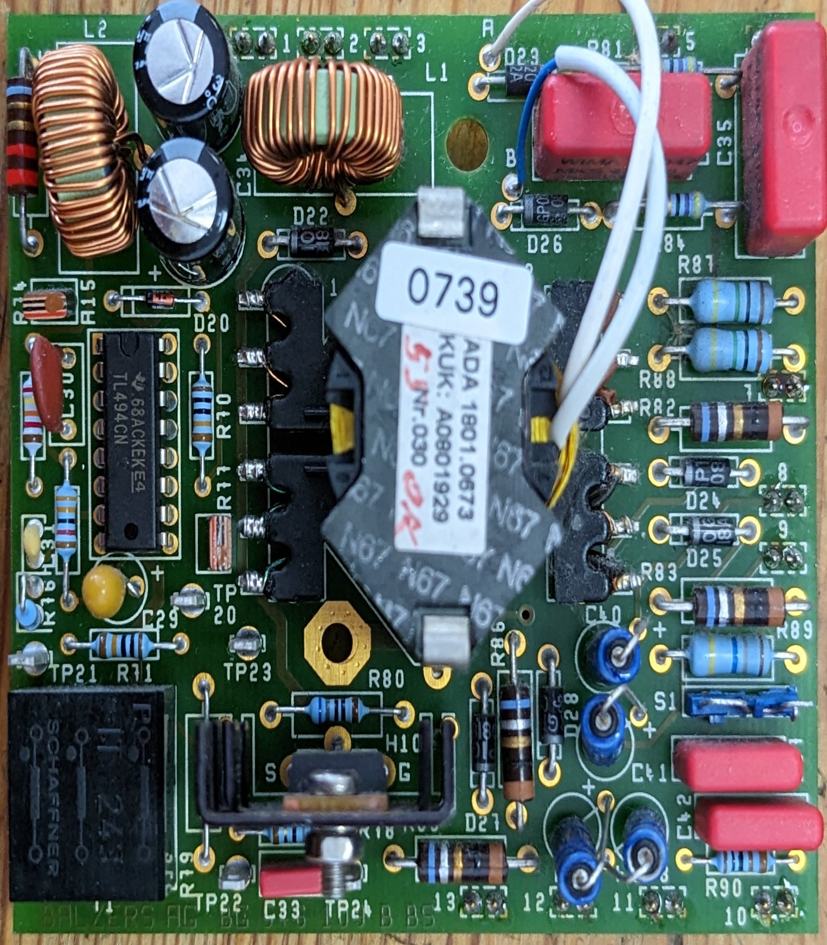
It produces 2x isolated +/- 40 V and+/- 500V for the DC-400-5 board. When hooking it up manually to +/- 24V it pulled no power and it was clear that further reverse engineering was needed.
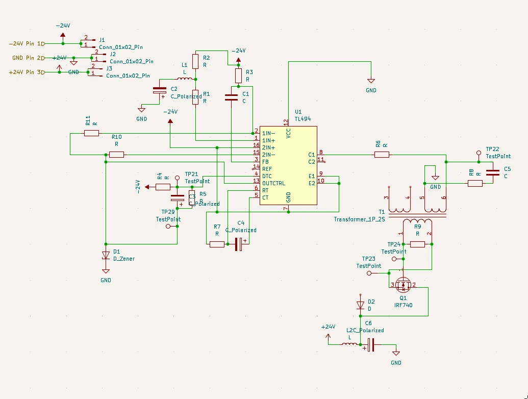
This is the primary side of the switching PSU. The schematic is unfortunately not perfect, but I’m planing to fully reverse the QMH-400 RF generator.
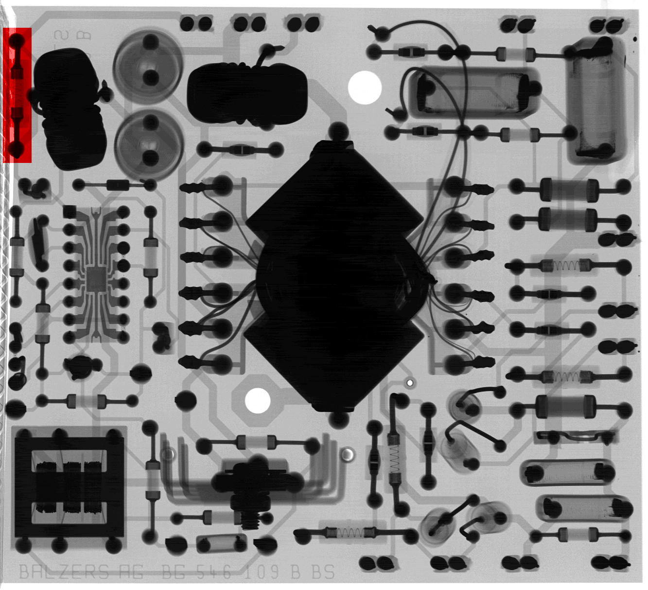
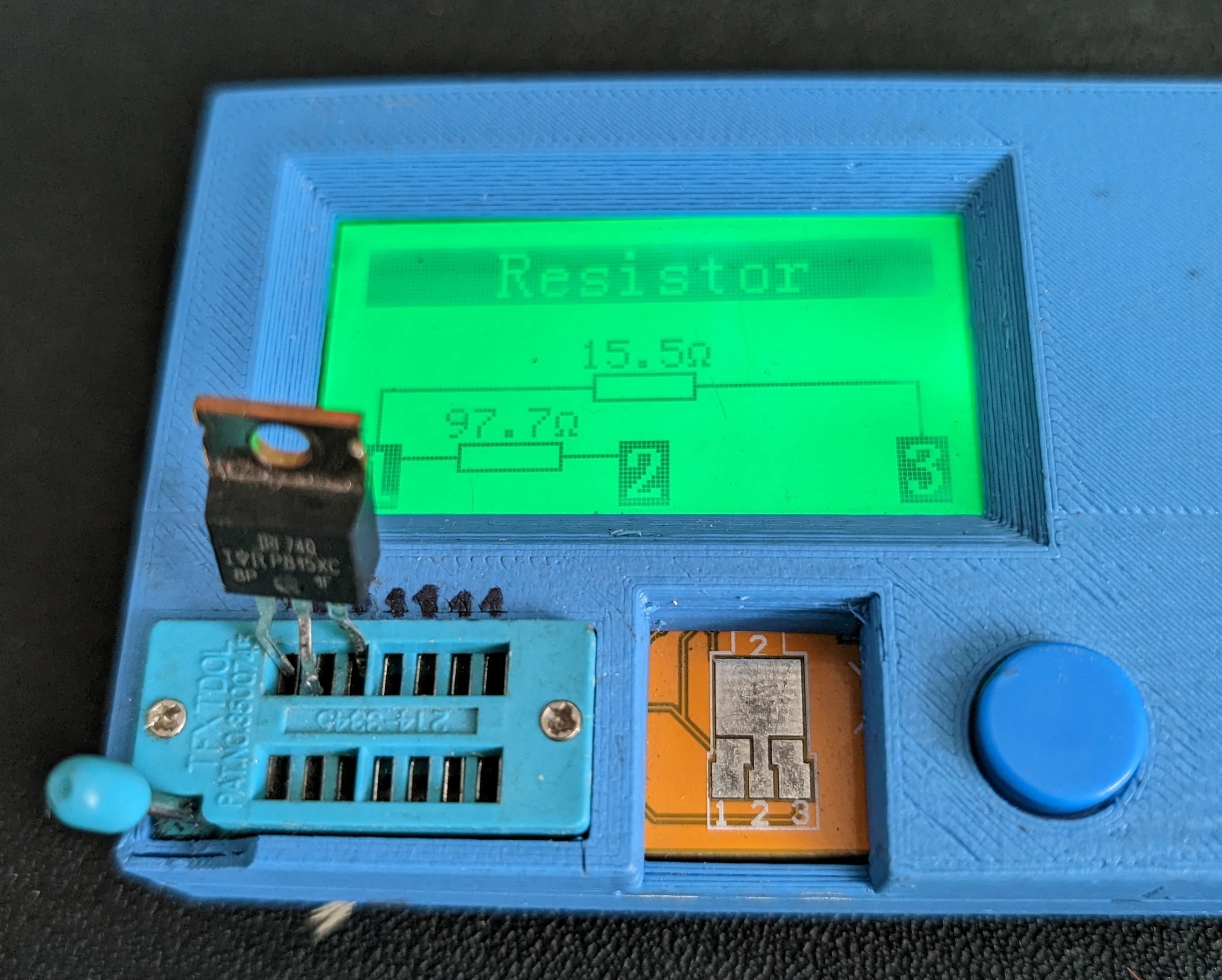
Looking very close on the X-Ray of the DCDC revealed a broken wire wound resistor on the input side of the PSU (marked in red on the X-Ray, the wire has a break on the lower end). Before reversing the board further I did not suspect this resistor to be broken because it had a very weird color code: red-red-gold-gold-blue. Turns out this is a 5 Ring Resistor with temperature coefficient rating. I did not know that temperature coefficient rating was possible with 5 rings, usually those are 6 rings.
Anyways, plugging in a new 2.2 Ohm resistor fixed this issue and on to the next: the switching mosfet got burning hot, pulling that out and putting it in a testers surprised me with a very strange failiure mode:
Unfortunately, just replacing the MOSFET did not help, the issue remained and the TL494CN seemed to work fine too. At this point it was clear, that something with the transformer had to have gone wrong. Pulling it out revealed something very unfortunate:
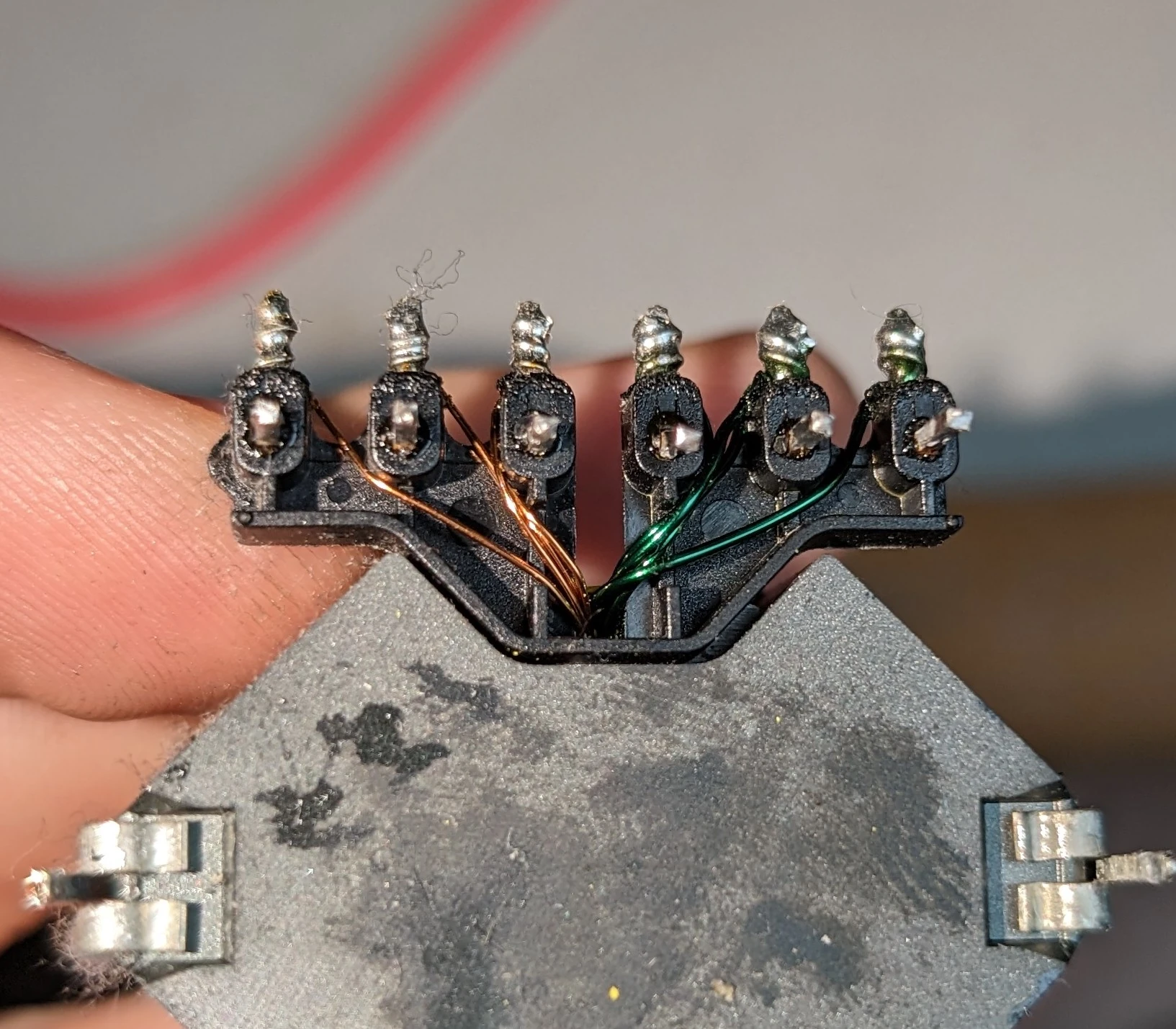
As can be clearly seen the right side of the transformer has badly burnt windings, even worse: it was custom built and no off-the-shelf part. So the next step was to unwind the transformer and reverse engineer that too the process of unwinding it was messy but it had to be done.
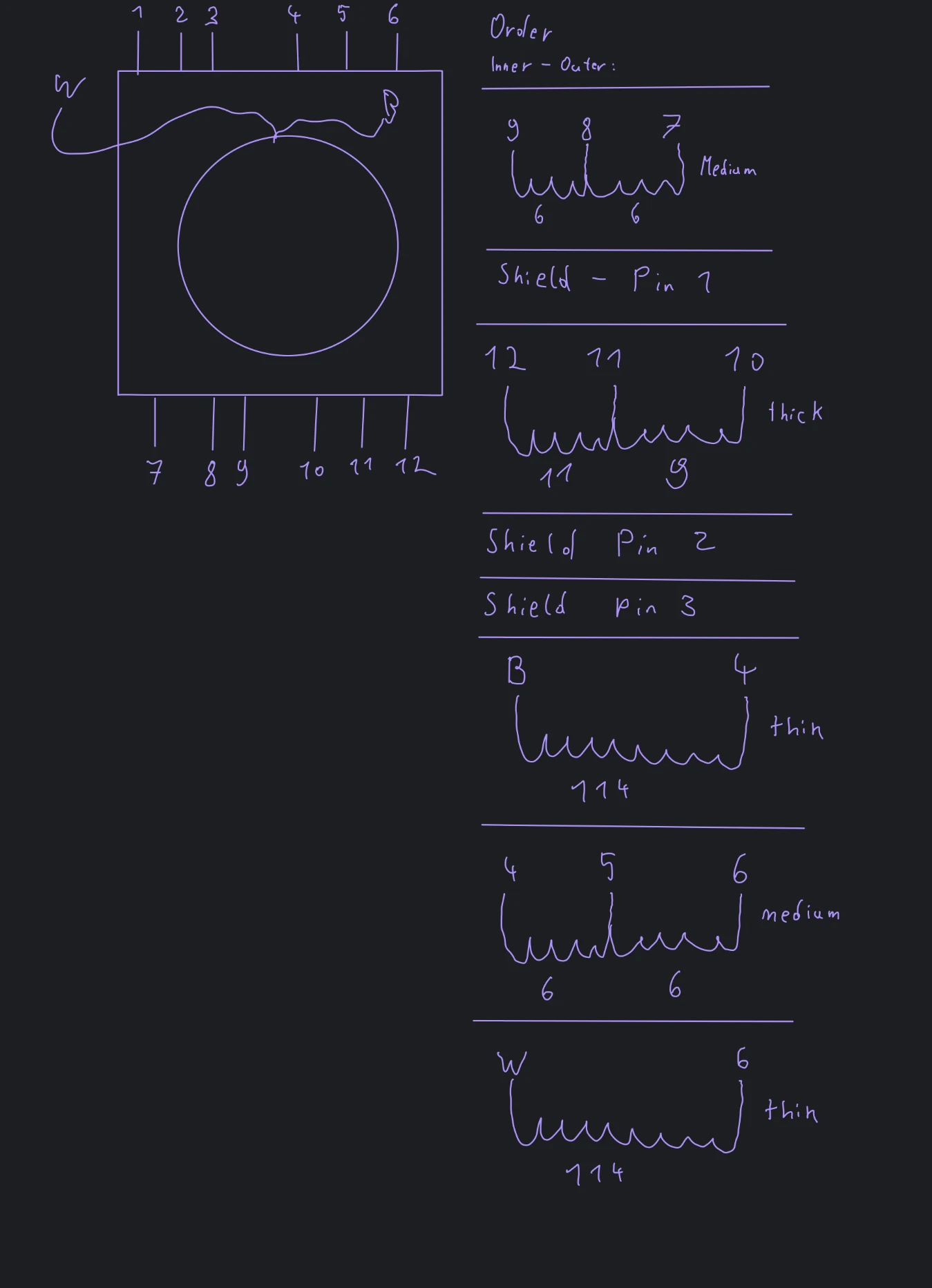
I was unfortunately unable to wind new HV windings (the windings with 114 turns), so I had to make a new supply for that. I still had a ZVS driver and ferrite core from HighVoltageShop laying around from another project so I decided to use that for a newly built, bypassed +/- 500V PSU. It was a good first try to see if the QMH-400 would work at all.
First meaningful results
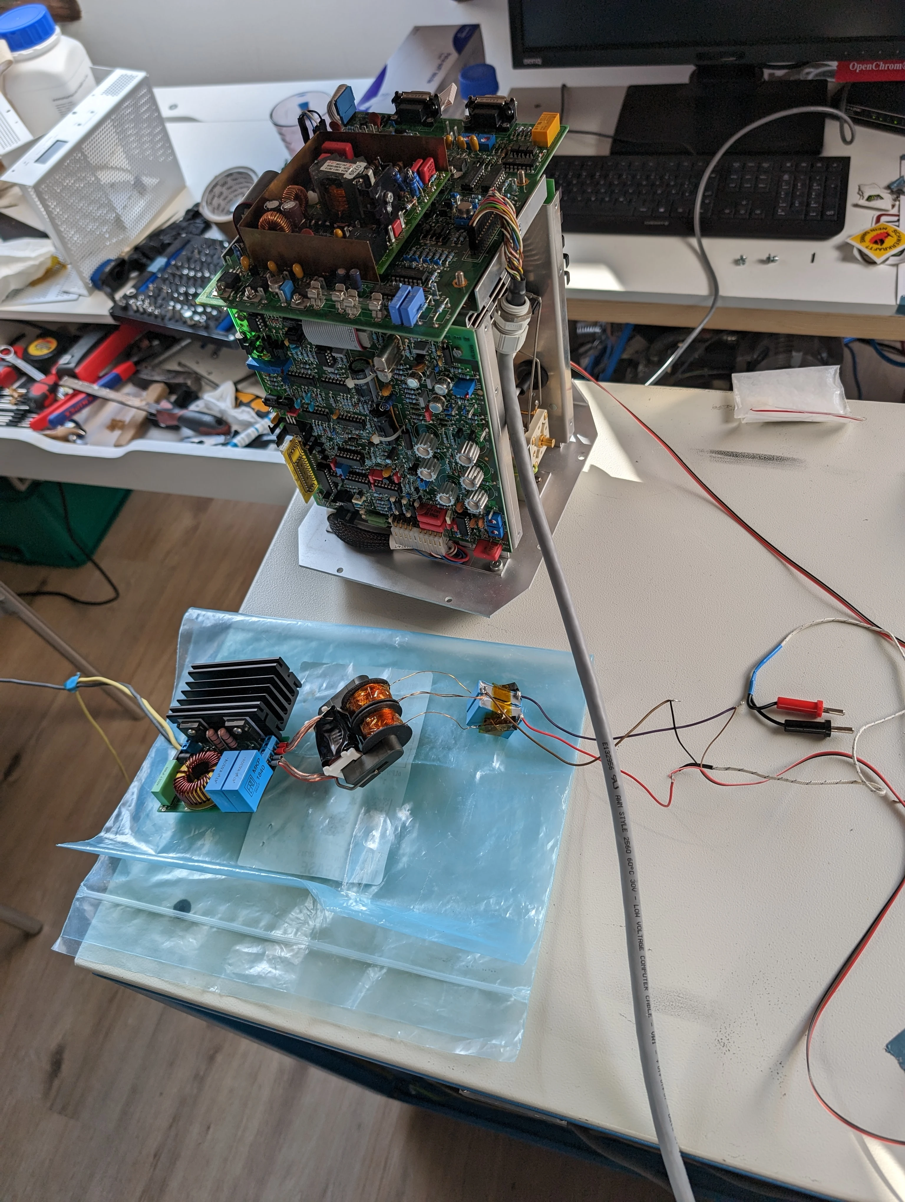
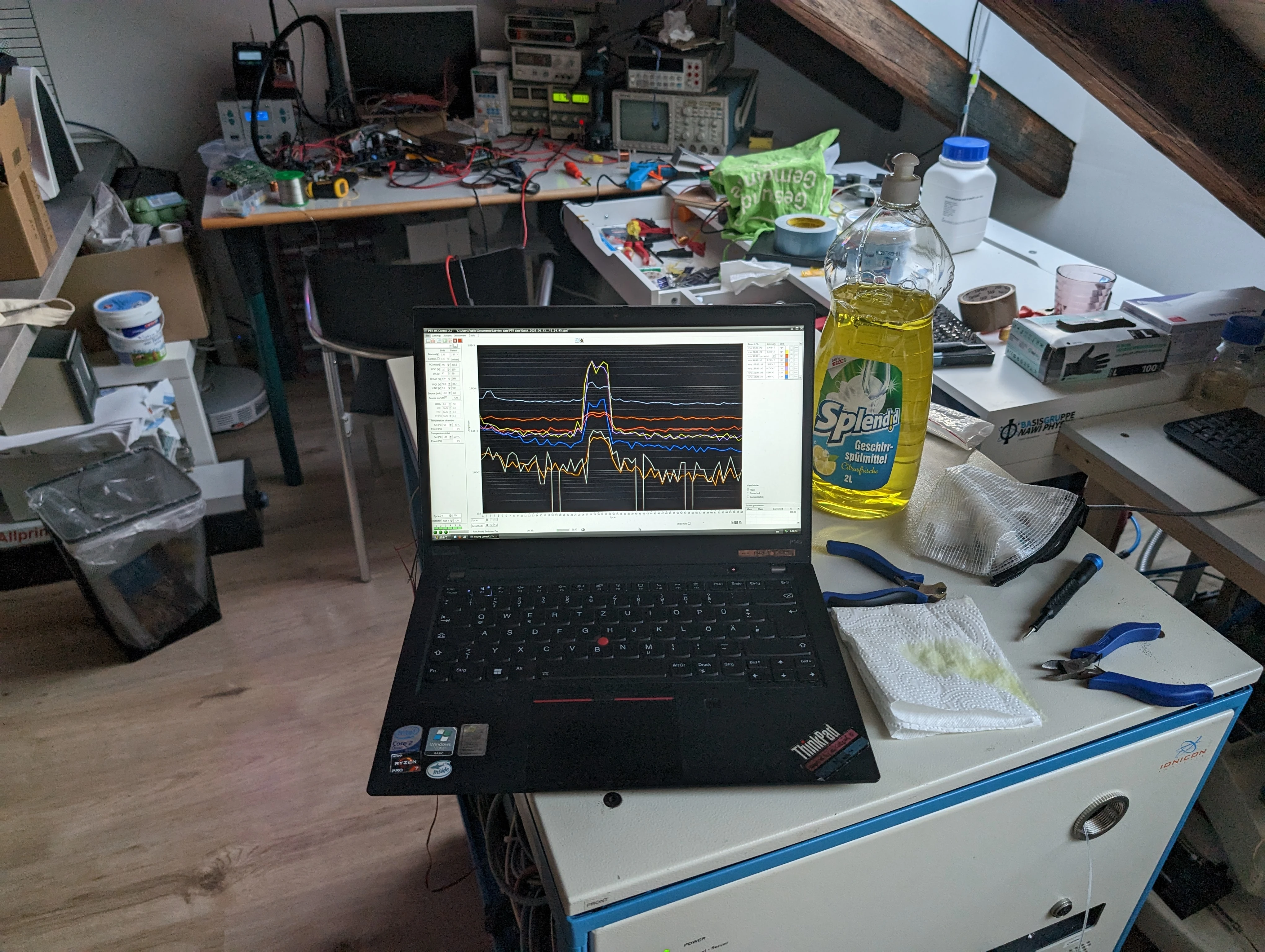
All parameters are currently not tuned. I still need to do that.
Yay! It seems like it’s at least somewhat operational now. A friend gave me the hint of trying to measure limonene in citrus smelling dish soap according to this paper. So I gave the marker masses a test:
What’s next?
Now that the PTR-MS shows first signs of life I think it’s time to clean it (that will be a lot of work…) and get it up and running perfectly down to the rated parts per trillion again. Also the janky PSU will be replaced by a commercial one at some point when I got the spare money for that.
I will continue to reverse engineer the QMH-400 frequency generator, hopefully some posts will follow regarding that during the summer break.
Also: if you have interesting and or funny ideas on what to measure with the PTR-MS feel free to reach out to me via Fedi, Mail or Matrix.
See you!